A sticky situation

Apologies up front. This is going to get a bit technical…
Hopefully, this figure will help you understand how everything relates.

The parts of the table specified.

Now that I have latch plates, it’s time to start the process of fitting them into the prototype. It’s straightforward:

Underside of the top showing one of the racks. The chalk marks denote the travel extents.

Begin by locating the stop plates (small, hardened metal plates which impact the stop rods during opening) in the table top. Install the stop rods in the aprons, using them to define the grooves in which they will eventually be housed. The extents of the table when open, and closed can be determined by positioning the top (and main box) in each state. Since the two pieces are connected through the mainspring barrel drive gear, this also governs the plate locations limiting the main box in grooves nestled out-of-sight within the aprons. Bolts visible within the side compartments of the main box protrude through its walls, and travel in these channels. With the open, and closed positions of the main box and top defined, the main box latch plate can be marked and mortised. As with everything in this project, sequencing is critical!

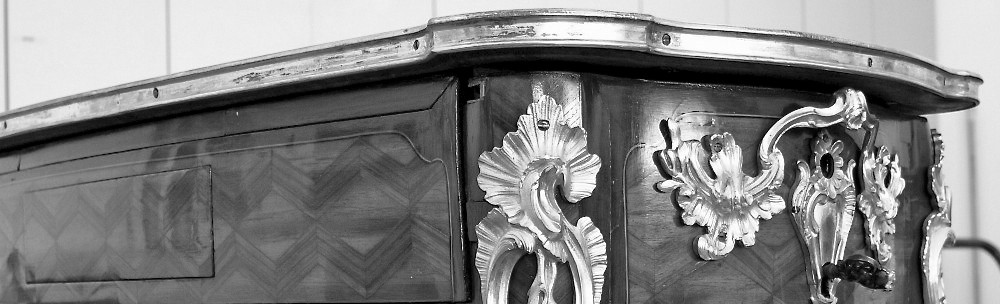
The prototype table (stripped to almost its essentials!) showing the areas of consideration.

So, I begin by reassembling the prototype carcass, and installing the racks and guides. For the moment, let’s leave the mainspring barrels out to simplify maters, and just concentrate on getting the top to move smoothly. Problem is, it doesn’t. It binds. Still. This was the issue three years ago when I first installed them. They were each slightly stiff, and needed to be “opened” a bit by the machinist. Now, individually they slide smoothly, and freely, but they’re still binding when assembled…

Observations and thought follow…

Consider that when the original table was built around 1750, micrometers weren’t a standard tool in an ébéniste’s kit (they still aren’t). So, while the various parts and pieces fit tightly together, it should not require fractions of a millimeter alignment to get things working.

Check each guide by holding a straight edge to its back – it’s ever so slightly convex, bulging into the travel path. Could this be the hang up?

Just a slice of light between the rack and rear apron.

The gaps in the back panel through which the top racks slide when actuated feel crowded – but we can see light between them, and the rack when deployed. Remove a few shavings to ensure clearance…

Could it be due to wood movement? It’s possible, but…

Following about 40 minutes of discussion with Jim, my studio “neighbor”, I realize the upper racks have been installed just slightly askew. Rather than the distance between them being identical at each end of the rack, they are farther apart on one end than the other. So, if I install the top from the rear of the carcass into the guides, it fits albeit tightly. However, when I attempt to slide the top into the carcass from the front, the racks are too far apart to fit into the guides. To compensate, remove one rack, adjust its mortise, then reinstall it. This can be prevented in the future version by using a spacer stick or panel during assembly. But that’s not the only problem in this case.

Underside of top illustrating out-of-parallel racks (lines exaggerated for clarity).

Turns out, when the top racks were installed they were set against the guides, marked, and fastened. This left no space between the guide and the vertical part of the rack where it passes the guide on its way to the top. What I’m feeling is that friction is increasing as the top is slid into the guides – the further it goes, the more these rub against one another. Try spacing the guides further apart, about 1 mm – friction decreases!

By opening this gap 1 mm, the top slides freely!

Eventually, addressing all of these issues I’m able to get the top sliding smoothly through the guides. When the mainspring barrels are added, and the top is pulled into its closed position, it gently swooshes into its open position when released. Success (finally)!

Mounting the top

With the mechanisms operating (somewhat) smoothly, it’s time to mount the table top. The process is fairly straightforward: place the carcass on the top, align the two, trace the racks onto the top, then mortise them.

image

Now comes the hard part…

According to Helmuth von Moltke, a Prussian military strategist, “No battle plan survives contact with the enemy.” When your plan meets the real world, the real world wins. Nothing goes as planned. Errors pile up. Mistaken suppositions come back to bite you. The most brilliant plan loses touch with reality (Lexician).

The mechanisms, now installed in the carcass, are stiff. They don’t move freely which is a necessity. Otherwise, the table will bind and won’t open. I began the investigation by checking each rack/guide individually outside of the table to make sure it moves freely. Ideally, they should slide by gravity alone when held vertically although sometimes, they require a push. My first “discovery” during this process was that the drive barrel was making contact with the lower guide. It left a “rub ring” around the barrel very near the gear (as shown in the above photo), and a shiny spot on the lower guide brass. After a quick consultation with Jon the machinist, I addressed these areas with a file to relieve material, and while it did prevent further contact, it did not rectify the problem.

Bright spot from contact with drive barrel

Bright spot from contact with drive barrel

Another thing to consider…

Even slight differences between the aprons and legs can be enough to cause the mechanics to “hang”. If the legs protrude even less than 1/32 inch out from the side apron the lower rack gets caught. I gently used a chisel with a swiping motion to bring the two surfaces flush. Depending on the severity, however, it still leaves marks.


My current thinking is that the rack is too closely fitted to the drive gear. That is, the rack and drive gear are so tightly positioned that it’s causing excessive friction in the mechanism. I’ll test this out by relocating the rack and guide slightly lower than it currently is, and report back.

While contemplating this issue a thought occurred. It would seem that the position of the lower racks/guides with relation to one another is not critical. In other words, they don’t really need to be aligned at identical heights in the aprons. So long as the main box is mounted squarely to them the height shouldn’t be a problem. We’ll soon see how this turns out.

Update (29 May): I adjusted the spacing between the drive gear and racks, in addition to relieving some “pinch points” in the guides, to get things moving. However, I think the change in temperature had the greatest effect on things. 

A mounting conundrum

Before we can proceed to shape the carcass, the mechanisms must be completely installed and operating properly. With the mechanisms in place, the challenge becomes mounting the main box and tabletop to them. The tabletop is relatively straightforward: center it on the carcass, then mark the top racks. The main box, however, isn’t so simple. Not only does it have to be located left/right, front/back within its opening, but it also needs to be situated in height above the carcass floor. If it’s too high, the bolt on the latch won’t catch; too low, and the bolt will drag on the main box as it opens. To complicate matters, it is impossible to directly mark any of these components. They’re buried deep in the carcass interior!

Being the case, I’ve devised the following plan…

  1. With the tabletop removed, center the main box between the lower racks in the carcass. This dictates the thickness of the shims that will be needed.
  2. Remove the top racks such that the main box can be lifted out versus slid through the front.
  3. Coat the latch bolt with graphite.
  4. Retract the latch bolt by turning the key, and place the main box into the carcass. Align it appropriately, then release the latch bolt. This should imprint a line on the underside of the main box where the latch makes contact.
  5. Align the back of the hole in the metal latch plate with this line.

While I’m certain some level of adjustment will be necessary, this methodology provides a plan to move forward. Such is the nature of product development or, to put it another way, if we knew what we were doing, it wouldn’t be called research!