Escutcheon plates

I received an unexpected parcel in the mail last week from Keith Turner, a woodworker in British Columbia Canada. Keith was inspired to make his own table after seeing the video from the Getty Museum. He’s also been following my progress, and sent replicas of the escutcheon plates that he cast. He writes:

I do have a background in the mechanical trades and teach at a local Institute of Technology, that is why I am able to cast as we have very well equipped shops. (I used to teach sand casting). These pieces were cast using the lost wax method and I put a blog together at http://lumberjocks.com/Longcase/blog/84378  if interested.

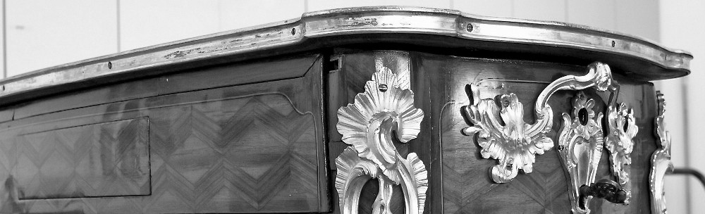
These are one of the components that decorate the carcass side aprons.

I must admit that this is one aspect of the re-creation that I have contemplated the least. I hadn’t realized, for example, that the escutcheons are not identical! Hint: look at the bottoms of the plates.

It’ll still be a while before I have to face this aspect of the project, but Keith’s gift has given me momentary insight into it. Many thanks, Keith!

Main box latch plate

I realized that hadn’t posted about the installation of the main box latch plate…

If you recall from the Getty video, this latch is positioned in the floor of the carcass, and releases with a key-turn in the proper left apron.

Top view of the carcass without the top & main box

This requires a (hardened steel) latch plate be mounted to the underside of the main box.

It is partially mortised to allow the latch bolt to have adequate purchase.

Locating it is fairly straightforward, I ran a pencil along the edge of the bolt to deposit graphite onto it. Then, operated it several times (in an attempt) to leave a mark on the bottom panel. Fortunately, working the main box back and forth also left a large scratch.

Now, for my next trick…

So as you have seen, the table’s mechanisms are (somewhat) working. Where do we go from here?

While there is satisfaction in reaching this point, there is still lots to do with the prototype. The small drawer latch must be mortised into the main box below the drawer opening. It requires two latch plates. There is also the matter of shaping the carcass aprons. I am thinking of leaving this partially complete as a pedagogical sample. I have seen this done before, where each leg shows a different state of progression, to great effect. Unless an interested buyer comes forward, this is my current intention. It would also be nice to create at least one proper Louis XV style leg (refer to previous attempts here, and here) before committing to the final piece!

With the exception of the small drawer latch, what remains is straightforward; almost no fiddling required. It will be nice to have a clear path for a change!

The light at the end of the tunnel could be the headlight of the oncoming train…

Main Box Stops, Continued….

In the last post on the topic, I concluded it would be necessary to drill holes in the lower racks to accommodate the stop bolts. The thought of this makes me pause because while the current piece into which they are being fit is a prototype, the racks and gears are not. The thinking goes that once the prototype is properly operating, the mechanisms will be transferred to the final oak piece, and the poplar prototype will remain for pedagogical purposes. At some point though, you just have to cut metal…

The procedure:

  1. Drill & tap the hole in the lower rack.
  2. Once this is done, use this new hole to determine where to locate the hole in the side of the main box.
  3. Finally, install the bolt, and use it to mark the extents of the groove in the apron.

Simple. Right?

With the aprons modified, reassemble the carcass, reinstall the mechanisms, and test (anxiously holding breath…).

Oops! Lower guide contacts the main box stop bolt.

$#@!

Unfortunately, I neglected the thickness of the guides when locating the bolt hole. After a brief walk to consider options, it’ll probably be best to reduce the diameter of the stop bolts to clear the guides. This won’t necessitate drilling another hole in the lower rack, and the 1/4 x 20 bolts being used for this are readily obtainable. It is a bit tedious, however, to file them down and still get them to thread into the racks.

The solution. Modify the stop bolt by reducing its diameter.

A final point. A careful inspection of the lower racks on the Getty original reveals that drilling the stop bolt hole in the incorrect location is not a unique problem. Apparently, I am in good company.

Many thanks to George Hamilton for his assistance tapping the bolt holes.