The main box latch

  
The main box latch is the trigger for the table’s entire mechanical system. When the key is turned within the right side apron, it actuates a lever releasing a bolt from the bottom of the main box. Under the tension from the drive mechanisms, the main box is propelled forward while, simultaneously, the table top slides back. Before proceeding with the mechanisms, it’s necessary to mortise in the main box latch. 

This is a bit of a delicate operation. The latch mechanism has a 90° bend where the key connects which has to be mortised behind the lower rack guide. It also has a sleeve into which the key is inserted. This needs to be contained within the apron, not protruding from it. 


After a bit of drilling, sawing, and paring things finally slide neatly into place!


Next, the long portion of the mechanism must be mortised into the floor of the carcass.


Lower racks and guides


Up to this point, we’ve seen the top racks and the drive mechanisms installed in the side aprons. The final pieces to address are the lower racks. While the tabletop attaches to and rides on the top racks, the lower racks mount and support the main box. Like the upper racks, the lower racks engage the drive mechanisms and span not only the apron, but also both legs. So, we need to be careful about their alignment. An additional complication is that the rear end of the lower guide is blind mortised into the rear leg, while the front end is grooved. The main box is supposed to be removed through this groove for assembly and maintenance. To hide them, the grooves get covered with dovetailed keys veneered to match the rest of the carcass, then covered with guilt bronze mounts. No one will ever know…

The shape of things to come


While making the prototype, I’ve had to keep the aprons rough to facilitate installation of the mechanisms. No sense in making them curvy when I’ll need to stabilize them for mortising. This week, however, the project is starting to turn a corner.

To install the lower racks, there need to be defined boundaries. Unlike the upper racks which extend beyond the carcass, the lower racks are contained within the carcass, and are unseen. This means knowing the extents of aprons once they’re shaped. I created a template from photos of the original, and referenced it from the center line on each side block. Repeat the process on the undersides. These lines can now be carried down the verticals on each leg for reference during final shaping. 

Reward Marquetry Prototype

 I recently received an e-mail from Joe, a Kickstarter backer, inquiring about the progress of the marquetry rewards. Looking back, I realized that this was the last time I posted on this topic. Much too long without an update!

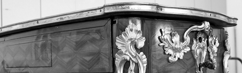
As discussed in that post, the red box in the figure shown below highlights the section I’m considering for the marquetry projects. I’m editing it to remove extraneous pieces that won’t make sense in that context, but it will include two flowers and a good portion of the ribbon binding the stems.

I used a modified double bevel technique for convenience. That is, the saw is held at a slight angle with respect to a line perpendicular to the surface of the veneer. This allows the top piece to perfectly conform to the bottom one when the waste is removed. No gaps! Veneer is cut two pieces at a time, each cut adding a new element. Slowly, the artwork takes shape.

Early stage marqutery prototype

Sometimes the pieces can become quite small and fragile. With this method, they don’t remain that way for long. They are quickly attached to the assemblage becoming part of the whole. The following image of the upper flower in-process provides a measure of scale.

Scale of the flower

Scale of the flower

As each flower is completed, it is cut into the background and the picture emerges. Once the piece has been mounted to its core, we’re looking at the back (glue) side in the image below, the binding paper is removed and a sealer applied. The lower flower can then be “engraved” and the resulting lines filled to add detail. There is still plenty of work to be done before this piece is “finished”.

Completed prototype

Based on my current schedule, I plan to begin working on the backer marquetry as soon as the prototype is finished. Probably, this summer. The idea is that by working the marquetry all at once I will become conditioned to its intricacies, my efficiency will increase, and this will put me in good shape to create the final piece for the tabletop.

Gnashing of teeth…


img_3104These are fairly sizable components for this piece. Housed within each of the side aprons, they provide the energy to make the table come to life. To make this happen the teeth on the large gear must align with those on not one, but two racks placed above and below it.

Demonstrating the alignment for the top rack and drive

The mortising process is straightforward. A hole slightly larger than the diameter of the large gear is created using an expansive bit which is then excavated to provide space for the rectangular section surrounding it.

With the cavity complete, a hole is bored through the apron for the winding axle. The operator will use this shaft to wind the mechanisms. Now the final placement of the drive can occur with the mounting plate mortised into the (interior) apron side.

Of course, nothing goes smoothly, and a bit of adjustment is required to get things appropriately integrated. There was a bit of an over correction during the first round, but nothing that a snippet of veneer and glue couldn’t fix. Number two went much quicker…

Left and right sides fit with drives and top racks

The next step is to mortise for the lower racks, the ones that connect to the main box.

Future location of the lower racks