Why Build Prototypes?

You might wonder why go through the effort of constructing a prototype when building a new piece? After all, it requires material, and at least as much time to create it, as the “official” piece. Why not just apply those resources to the finished piece?

So here’s my story…

I embarked on this Oeben re-creation, after much study, by constructing a three-dimensional SketchUp (SU) model. The thought being build it in SU to work out the bugs in the process. This may come as a surprise to you, but ALL of the aprons on this table exhibit a curve to some degree (fortunately they’re not compound!). There are very few flat exterior surfaces on the piece! At the time, I thought the easiest way to handle this would be to begin with thick material, then shape it appropriately. I drew it this way, and didn’t look back. Life was good… Or was it?

Now it comes time to cut wood. So, I choose an appropriately thick piece of stock for the “Main Box” front. The “Main Box” being the “drawer” that extends forward when the top is released and retracted. It contains all of the other “hidden” components. For several weeks, I continue working – yet, something keeps bothering me. Each time I look at the curve for the front, it seems out of place, like it’s inappropriate, and not representative of what I see in the original. Finally, I sit down, and look through the photos. I come across an image taken of the bottom. It’s available on the Getty Museum’s website. I’m showing an outline of its shape below. The two open spots at the bottom are where the legs protrude.

20140126-192353.jpg

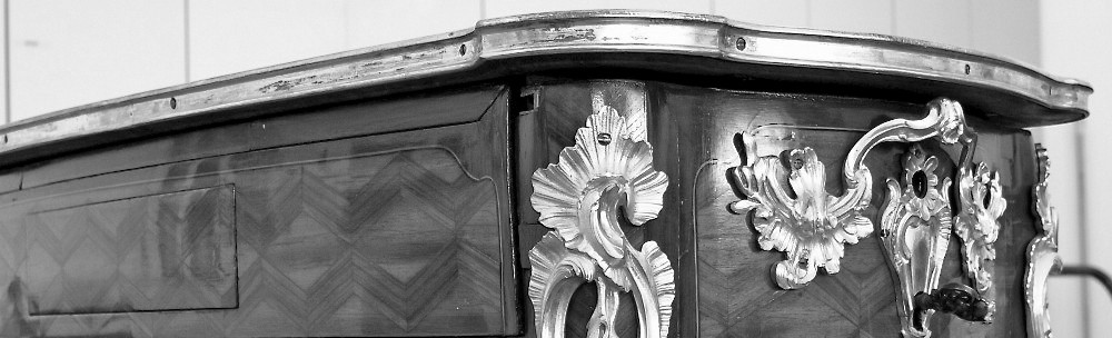
From it, I calculate the extent of the curvature at its most extreme, and learn that my drawing is about 1.5 cm too shallow. Not necessarily a show stopper. But wait – I look closer. Not all of the aprons were created in this fashion! It appears that the board comprising the rear apron was bent. Looking further still, I come across this photo showing the underside of the “Main Box”.

20140122-155831.jpg

It shows a uniform thickness board bending in a gentle arc composing the front of the “Main Box”. So, it appears that my plan to work a thicker board to shape is incorrect. Now the question becomes how did Oeben’s craftsmen accomplish this?

There are several methods for creating curves in wood. The most basic is to cut perpendicular kerfs along its inside. This leaves voids allowing room for compression. However, these spaces are highly visible, and from the previous picture, not in evidence in this table. A second method involves slicing the board into thin planks along the grain then gluing them back together while clamped to a form. Once the glue dries, the board maintains the shape. I have witnessed instances where this was done and difficult to detect, but I don’t believe that this method was used either. A third procedure involved steaming the board and bending it. While this seems to be plausible, was this historically correct for the period in which the table was made?

Following a brief exchange with Patrick Edwards, this appears not to be the case. According to Patrick:

Oeben did not steam bend furniture.  French curves are sawn from solid wood.  Although Denis Papin (1647-1712) invented the steam pressure cooker, no one thought to use it to bend wood until the 19th century.  Complex two dimensional curves are “sculpted” as you suggest using chisels and scrapers.  Final truing of the surface was with toothing planes.

So, my initial methodology was correct, and the aprons were hewn from thicker stock.

If I hadn’t taken the time to construct the prototype, I may have missed out on this learning opportunity. Not only do prototypes help you work through unforeseen issues that weren’t caught during the modeling phase, and provide valuable practice for building the final version:

If you can’t get it right on the prototype, how do you expect to get it right for the final piece?

The process of creating a prototype gives insight into how the piece was originally made – living archeology, if you’re paying attention!

So, what becomes of the current prototype now that this issue has come to light? After all, good material and effort has already been expended to reach this point. Rather than discard it, I decided to laminate material and “thicken it up”, upon consideration. While this will allow me to obtain the appropriate external shape, the interior will remain as it is presently. It’s a compromise I will live with for now…

Progress Report: Prototype Main Box

Back in October, I spent one week in Franklin, IN focused on beginning the prototype construction starting with what I term the Main Box. This is the “drawer” that extends from beneath the top when the mechanism is released. Being what feels like perpetually behind, I wanted to post a series of pictures showing the progress from that point up to now.

20140102-220051.jpg

Cutting dovetails for the Main Box carcass.

In the image below, note that the sides of the Main Box carcass stand above the rest of the case. This accommodates the flaps that cover the interior compartments to either side. Observant readers will also note that these are square in profile rather than angled at a 45° bevel. I purposely left them in this state to prevent damage to the prototype at this stage. Rather than measuring, there is a fair degree of fitting and scribing based on the shapes of the existing components. The sharp arrises would be absolutely chewed up during this activity, so I thought it best to leave them square. This will be addressed just prior to glue-up.

20140112-151649.jpg

Main Box frame.

Note that in the picture above, the front is flat not curved as the original. This too will be fixed prior to glue up. When working with curvy and complex profiles, it is sometimes best to leave the surfaces flat not only to prevent damage, but also to facilitate layout, clamping, etc.

Attached to the rear of the Main Box is a piece that covers the gap between the table top, and the flaps and book rest. This strip follows the profile of the top in its deployed position, and must be “scribed” directly from the top, then adjusted to fill the necessary space. To do this, I used the template I created to shape the top marked with additional information on the extents of the components when fully open.

20140111-222321.jpg

Positioning the top and Main Box to layout the “cover strip”, a profiled wooden piece mounted to the top rear of the Main Box.

20140111-222646.jpg

Detail of the “cover strip”.

One of the more straight forward tasks was the creation of the small “hidden” drawer that fits in the center section of the Main Box…

20140102-220108.jpg

The Main Box carcass with “hidden” small drawer installed.

…which gets covered over by a thin wood panel, and the “cover strip” when assembled.

20140111-222936.jpg

Main Box with “cover strip”, and center panel in place.

The next task is the creation of the two flaps the over the “hidden” compartments on each side of the Main Box. Using frame and panel construction with a complication, a tenoned or splined miter for frame joints, these too get scribed to their adjacent components.

20140118-165112.jpg

Two of the flap frame pieces showing the splined miter.

20140118-165144.jpg

The splined miter from the inside vantage.

20140118-165203.jpg

Flaps overlaid on the Main Box carcass ready to be trimmed.

Finishing out the Main Box will be the book rest. It will be composed of a similar frame and panel assembly.

Sticking together

Woodworkers have a variety of glues at their disposal. No one is the universal panacea – each has situations in which it excels. Since I chiefly build indoor wood furniture, I usually use hide glue.

20140102-215419.jpg

Hide glue comes in two flavors: hot, and liquid. The terms are self-explanatory. At the risk of redundancy however, I will elucidate. In the United States, hide glue is most readily available to woodworkers in a powdered form at two strength levels. Denoted in grams, the lower the number the longer the open time. 192 gram strength hide glue is the most common. While suitable for most woodworking tasks, its speciality is in veneering and marquetry. Also available, but much less commonly encountered is 251 gram strength glue for cabinetmaking. This glue creates a stronger bond, but sets up much faster than 192.

  • Hide glue is easy to use. Other than the heating that hot hide glue requires, it is simple to prepare, and use. Liquid hide glue can be used straight from the bottle!
  • Hide glue is strong. It is more than adequate for woodworking tasks. In certain joinery situations, it even provides a slight advantage.
  • Hide glue doesn’t smell. Many people are concerned that hot hide glue will produce a strong smell, according to the stories they’ve heard. However, visitors to my studio are always surprised to learn that the glue pot has been cooking their entire visit, and they’ve been standing adjacent to it! Use a good quality hide glue. If the glue develops a strong smell, it’s an indication that it has gone bad. Wash out the pot, and make a fresh batch!
  • Hide glue has an infinite lifetime if kept dry.

While many are familiar with these points, few are aware of its benefits.

  • Hide glue is reversible! Unlike nearly every other glue, pieces bonded with hide glue can be separated with the application of heat and moisture, that is, hot water! Every other glue that I know of requires the destruction of the joint!
  • Hide glue adheres to itself. It is the only glue of which I’m aware that will bond to itself. This quality makes it ideal in situations where the joinery is stressed, and will eventually fail, for example, chairs.
  • Hide glue is transparent to finish.
  • Hide glue accommodates certain techniques, such as rubbed joints, and hammer veneering, for instance, which cannot be achieved through any other method.

20140102-215411.jpg

Not only does hide glue provide these advantages, but this is exactly the type of glue that would have been used on the Oeben original.